
Many thanks to Jeff Jordan, our Electrical & PCB Product Manager for his ideas, guidance, and automotive know-how. We took advantage of the Parametric study tool to simplify and automate the design iteration process, enabling users to find optimum operating points with minimal user intervention.

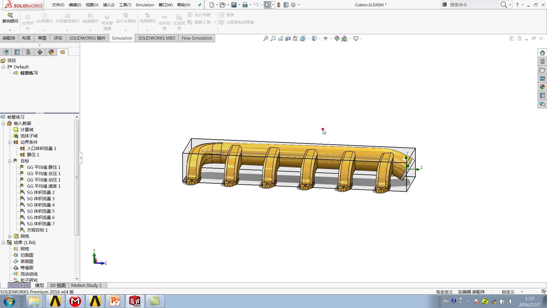
Using SOLIDWORKS Flow Simulation, we were able to redesign the box-shaped manifold to improve air-flow performance. There was a major improvement in the airflow through the first runner with the design change. Here is a table comparing the results between the boxed design and the dual-plenum design.

This plot shows that the flow through the primary plenum is uniform, free of any localized accelerations and dead spots.īesides a small portion at the nose of the plenum, the velocity cut plot also indicates this flow uniformity through the manifold and runners, free of any recirculation areas. This is evidenced by the airflow trajectory plots in Flow Simulation. While we established the efficiency of the airflow distribution through the Standard Deviation parameter, we will still need to ensure that the manifold volume is being optimally utilized. Design Mod – Dual Plenum Manifoldįigure 8: Air Flow Trajectory animation through optimized manifold This called for major design improvement. It is essential to keep this number as close to 0 CFM as possible for a good design. The Standard Deviation is a convenient statistic that keeps track of how far a set of values diverge from their mean value (In our case, the mean flow rate is 75 CFM since the 300 CFM inlet flowrate is distributed across 4 runners). It is important to note here that I used ‘Standard Deviation’ to measure the air distribution between the runners. The manifold shape is also not optimized for airflow as evidenced by the recirculation areas (D) from the velocity cut plot.The goal table indicates that the runners aren’t balanced with a Standard Deviation (SD) of 3 CFM! While the 4th runner operates at 78 CFM, the 1st runner operates at 71 CFM.

From these results, there are a few things we can establish: We used 2 results to study the performance of the manifold – A cut plot of the air velocity through the manifold and a Goal Table for the Volume Flow Rates (VFR) through the runners. Figure 4: Results from Flow Simulation – Velocity Cut Plot (Left), Goal Table (Right)


 0 kommentar(er)
